Complex impedances
Thevenin's theorem and how to use it.
Dynamic range
Gain
Current and voltage sources
Binary and Hexadecimal numbers
Unipolar and bipolar signals
Complex
impedances
The impedance of a resistor
is well known, ie. R, and very simple, as it is a real number. It just
expresses the ratio of voltage to current across it in any circuit, R =
V/I. Capacitors and inductances are frequent components in other circuits
and they also have an impedance which, unlike a resistor, is complex because
they introduce a phase change between current and voltage, so the ratio
V/I is no longer capable of being summarised by a single number.
For a capacitor C, Z = V/I = 1/jwC, while for an inductor L, Z = jwL. After this, we can work with Cs and Ls just as easily as Rs, provided we are ready to manipulate complex numbers instead of just real ones. For example the impedance of two resistors in series is Zseries = R1 + R2. In the same way, the impedance of two inductors in series is Z = jwL1 + jwL2. = jw(L1 + L2).
The parallel impedance of a capacitor, C, and a resistor, R, can be calculated from the knowledge of the results for resistors, Z = R1R2 /(R1+R2). Z = R(1/jwC)/(R+1/jwC) = R/(jwCR+1). Once this is known, you can combine more resistors and capacitors in just the same way as for resistors alone. Similarly with inductors.
Eventually, you will end up
with a complex number which, like all complex numbers can be written as
an amplitude and phase factor, ie Z = Z0exp(jf).
It is not always necessary to do this, and sometimes the result can be
rather nasty algebraically, but there is no need to be intimidated. It
can be manipulated with complex algebra if required.
Back to top
Thevenin's theorem and how to use it.
The theorem tells us how to
simplify a complicated network into a voltage source and a series resistor
(or complex impedance). The rule is that the Thevenin voltage Vthevenin
= the open circuit voltage (imagine an ideal voltmeter, which draws no
current, attached to the output of the circuit). The Thevenin resistance,
Rthevenin, can be calculated from the Thevenin
voltage divided by the short circuit current. The short circuit current
is found by calculating the current which flows when the output terminals
are connected together. Once you've tried it out on a circuit, it is easy
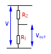
to understand. Take as an example a potential divider connected to a voltage
V, ie. two resistors connected in series, with the output voltage taken
across one of them.
| Vopen
= VR1
/(R1+R2)
= Vthevenin
Ishort
= V/R2
Rthevenin= Vopen/Ishort = R1R2/(R1+R2) |
 |
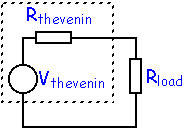
Equivalent circuit |
It can also be applied to networks of complex impedances, not simple resistors.
Binary
and Hexadecimal numbers
A binary number is a number
expressed to the base 2, to be compared to a decimal numbers with
which we are all familiar which use the base 10. A hexadecimal number
uses the base 16. What this means is:
In a base-N system the digits available are 0, 1,... N-1. Thus, in the base-10 number system the digits are 0, 1, 2, 3,... 9 while in the binary system the digits available are simply 0 and 1. In the hexadecimal system we need to give digits greater than 9 a code, so we use A, B...F to represent 10, 11, ...15.
In all number systems the digits
are written in powers of the base, with the rightmost digit repesenting
the lowest power. Thus the number 967 (decimal) means
9 x 10²
+ 6 x 101 + 7 x 100
Similarly, in binary
the number 10011 means
1x24
+ 0x23 + 0x22 + 1x21 + 1x20
= 1910 where the subscript 10 indicates the base,
ie decimal. So this could also be written 100112 in case of
any ambiguity. Thus the number AF1B16 means 4482710
Binary numbers are used in all computers, where normally only two states are available, OFF and ON, or HIGH and LOW. But lengthy binary numbers are tedious to read and compare so the Hex representation which effectively groups 4 binary digits into one Hex digit is useful. Two Hex digits make one byte, or 8 bits, which is a very commonn way of grouping bits in computers or microprocessors.
Another term which is encountered
in microprocessor or computer arithmetic is the complement of a
number. There are two kinds: the "one's complement" just exchanges 0 for
1 and vice-versa, while the "two's complement" is the "one's complement"
+1. Some examples
Back to top
Decimal Hex Binary One's complement
Dynamic
range
The dynamic range of a system
is the ratio of the largest to the smallest signals in a system. It's easy
to understand why there should be a largest signal, either because no larger
signal is physically possible, or because the system is limited, eg by
amplifier saturation, to a certain maximum amplitude. The smallest signal
usually arises from another kind of limitation, eg the smallest signal
distinguishable from noise or the minimum digitisation level (1 bit) of
an Analogue to Digital Converter. The dynamic range is expressed in a number
of units:
a number (eg 20,000), a number
of bits (eg 8bits, or 28 = 256) or dB (eg
60dB = 1000, if the amplitudes are voltages).
Back to top
Current
and voltage sources
Current and voltage sources
are what their names suggest, ideal sources of constant current or voltage.
I.e. they produce a given current or voltage no matter what the conditions.
The most likely condition to vary will be the load resistance or impedance
to which the source must deliver its current or voltage. So, in practice,
it is not realistic to expect a current source to be able to deliver a
constant current into a high impedance load; eventually the voltage across
the load will have some influence on the source. Similarly, a voltage source
will not be able to deliver a constant voltage if the load resistance becomes
too small; it simply will not be able to supply the large current required.
Nevertheless, good approximations
to ideal sources can be found, provided reasonable limits are set on the
range of current or voltage. The simplest current source is simply a voltage
in series with a resistor. It should be obvious that a series resistance
load will influence the current but a transistor as load may not affect
it so much.
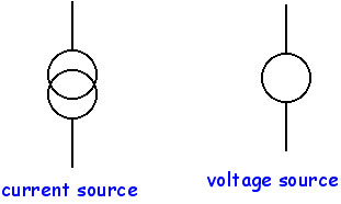
An ideal current source has
a high impedance, while an ideal voltage source has a low impedance. The
symbols are shown below.
Back to top
Gain
This refers to amplification,
in the most general sense. The gain of an amplifier is the factor by which
the input signal (normally voltage or current) is multiplied. Although
in general we are interested in systems with amplification factors greater
than one, gain can be greater than, equal or less than unity.
Back to top
Unipolar
and bipolar signals
Just refers to signals which
have one polarity (ie either always greater than zero, or always less than
zero). An example is a simple exponential - v(t) = exp(-at), which never
falls below v(t) = 0. Bipolar signals are those which have both positive
and negative amplitudes (such as a sine wave). Of course we can also refer
our zero level to a constant value if we wish.
Don't confuse bipolar signals
with bipolar transistors - they are completely unrelated.
Back to top