Trip-T Front End Board Documentation Home
Trigger Primitive Generation Functionality
Disclaimer
Please note that the implementation described here is documented here
as a call for feedback from those involved in the trigger algorithm
specification. At present there is no deployed version of this
algorithm.
Overview
The trigger primitive generation falls into two groups: the off-axis and Ingrid.
Ingrid requirements are:
- "horizontal" channel discriminator logical OR (24-way);
- "vertical" channel discriminator logical OR (24-way);
- programmable "horizontal" and "vertical" gate generation;
- gate coincidence;
- global trigger primitive signaling.
The preliminary off-axis TFB cosmic trigger functionality requirements were
-
discriminator gate generation of programmable length;
-
bad/inactive channel mask;
-
programmable channel pairing for double ended scintillator instrumentation;
-
regional summation of the active channels;
-
programmable active channel count threshold (i.e. global per TFB);
-
global trigger primitive signaling.
I'll go through the approach I've used to address each of these
points, hopefully delimiting the scope and highlighting some of the
advantages and disadvantages present. Additionally, I'll explain any
programmable parameters associated with the module.
The following subsections occur in the same order as the data flow
through the system, starting with the discriminators and finishing at
the cosmic accept output sent to the CTM. Ingrid is discussed first,
then the off-axis module.
Ingrid
Channel Mask
The all 64 discriminator inputs are passed through a logical AND with
a configuration bit as a way of enabling the channel. Although the
same configuration space registers are used as for the off-axis
module, the mechanism is slightly different. Once this stage has been
passed the AND array output is passed to the logical OR.
Logic OR and Channel Division.
The channels are divided up into two groups, those from TripT A and
TripT B (group AB) and those from TripT C and TripT D (group
CD). These channels are arranged on opposite sides of the TFB, see
TFB_V2_photo_top.pdf.
A cascade of 4-input OR gates is used (the s3 uses 4 input LUTs, so this
modularity is convenient).
The first stage is formed of 2 arrays of 8 of such gates, ORing the 2
groups of 32 signals into 2 groups of 8 signals.
The second stage has 2 pairs of the same type of OR gate, producing 2
outputs for each pair.
A standard 2 input or gate pair produces the
final output for each pair.
Gate Generation
Each output is then fed into a separate instance of the same type of
gate generator as is used at the input stage of the Off-Axis
algorithm. In addition, the same register is used to set the gate
length as that for the Off-Axis detector.
The outputs of these gate generators are passed through a logical AND,
the output of which is the accept signal that is transferred to the
CTM, see the section below on "Algorithm Selection".
Off-Axis
Gate Generation and Channel Masking
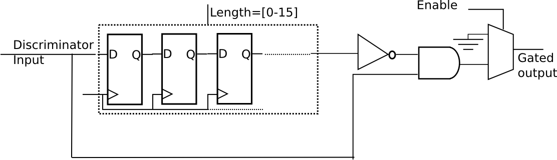
Once triggered, the TripT discriminator outputs remain latched until
the preamplifier reset is asserted. It is thus necessary to use the
rising edge to generate a coincidence gate for each channel. This is
implemented using a variable length shift register and some glue logic
to refer the input to the delayed output. See Figure 1.
Note that this module has been verified to work using the geometrical
cosmic trigger used at IC.
One of these modules is instantiated per TripT discriminator output, there are, thus 64 per board. The length parameter is exposed to the user as a global parameter, that
is, there is one gate length specified per TFB and that is applied to all 64 inputs.
The other user accessible control present is the Enable signal. This
is present on a channel by channel basis and provides a route through
which an individual channel can be masked out. The masking here is shown
schematically as a multiplexer connected to the output of the glue logic.
The module is clocked at 100MHz, permitting the gate duration to be varied from
0ns to 160ns.
Channel Pairing
TFBs instrumenting the SMRD will be arranged to readout the SiPMs from
both ends of the scintillator bars. Requiring paired hits for channels
not involved in this kind of geometrical arrangement is clearly
nonsensical. A programmable mapping is thus implemented to permit the
user to switch between unpaired active channel counting and two types
of channel pairings.
The basic logic requires that both paired channels be active before
either will count (once) to the global count of active channels. This
functionality is global, i.e. once a given TFB has been set up to
perform channel pairing, it will affect every channel on the board.
There are two mappings, termed (1) Opposite and (2) Adjacent. Explicitly, these
pair like-numbered channels as follows:
| Mapping (1): Opposite |
| TripT [Channel Index] |
TripT [Channel Index] |
| A[0] | D[0] |
| A[1] | D[1] |
| A[2] | D[2] |
| A[3] | D[3] |
| A[4] | D[4] |
| A[5] | D[5] |
| A[6] | D[6] |
| A[7] | D[7] |
| A[8] | D[8] |
| A[9] | D[9] |
| A[10] | D[10] |
| A[11] | D[11] |
| A[12] | D[12] |
| A[13] | D[13] |
| A[14] | D[14] |
| A[15] | D[15] |
| B[0] | C[0] |
| B[1] | C[1] |
| B[2] | C[2] |
| B[3] | C[3] |
| B[4] | C[4] |
| B[5] | C[5] |
| B[6] | C[6] |
| B[7] | C[7] |
| B[8] | C[8] |
| B[9] | C[9] |
| B[10] | C[10] |
| B[11] | C[11] |
| B[12] | C[12] |
| B[13] | C[13] |
| B[14] | C[14] |
| B[15] | C[15] |
and:
| Mapping (2): Adjacent |
| TripT [Channel Index] |
TripT [Channel Index] |
| A[0] | B[0] |
| A[1] | B[1] |
| A[2] | B[2] |
| A[3] | B[3] |
| A[4] | B[4] |
| A[5] | B[5] |
| A[6] | B[6] |
| A[7] | B[7] |
| A[8] | B[8] |
| A[9] | B[9] |
| A[10] | B[10] |
| A[11] | B[11] |
| A[12] | B[12] |
| A[13] | B[13] |
| A[14] | B[14] |
| A[15] | B[15] |
| C[0] | D[0] |
| C[1] | D[1] |
| C[2] | D[2] |
| C[3] | D[3] |
| C[4] | D[4] |
| C[5] | D[5] |
| C[6] | D[6] |
| C[7] | D[7] |
| C[8] | D[8] |
| C[9] | D[9] |
| C[10] | D[10] |
| C[11] | D[11] |
| C[12] | D[12] |
| C[13] | D[13] |
| C[14] | D[14] |
| C[15] | D[15] |
The data are latched at the output of this stage.
Active Channel Summation
The output from the pairing multiplexer is fed into the input of the
summation module. In order to avoid a time consuming loop over the
input channels, a divide and conquer approach was used.
This is implemented as a multi-stage cascade of 2-input adders, of
increasing width. The 1st stage uses 32 x 2-input, single bit wide
adders that output a 2-bit summation. The 64 channels are paired and
assigned. In the paired trigger mode, this stage simply has half the
inputs permanently set to zero. The output of this stage feeds the
next, which comprises an array of 16 x 2-input, dual bit wide
adders. This second array produces 8 x 3-bit summations of the input
data.
The cascade continues until there is one 2-input, 6-bit wide adder
that produces the 7-bit total.
A register stage has been placed between the output of stage 2 and
input of stage 3, where there are 8 x 4-bit results. I don't yet know
what the performance of this part of the system will be.
Note that in either of the Paired modes, the maximum output is 32,
whilst in un-paired mode, it is 64.
Accept Threshold
The registered output of the summation module is compared with a 7-bit
user programmable threshold. If it is found to be greater than this
number, the event is considered a cosmic accept and the primitive is generated.
Algorithm Selection
Both the Off-Axis and Ingrid algorithms are present in the firmware
and reside side by side. Additionally, both are active at all
times. The accept signals from each are fed into a multiplexer used to
select between the two. The output of this mux drives the primitive
signaling engine described in the next section.
Global Trigger Primitive Signaling
A local accept is transferred to the CTM via a 100ns long pulse. The
TFB provides the ability to set this pulse length in steps of 10ns
with 8-bit range, i.e. [0,255] = 0,2550ns. Additionally, this signal
has programmable polarity.